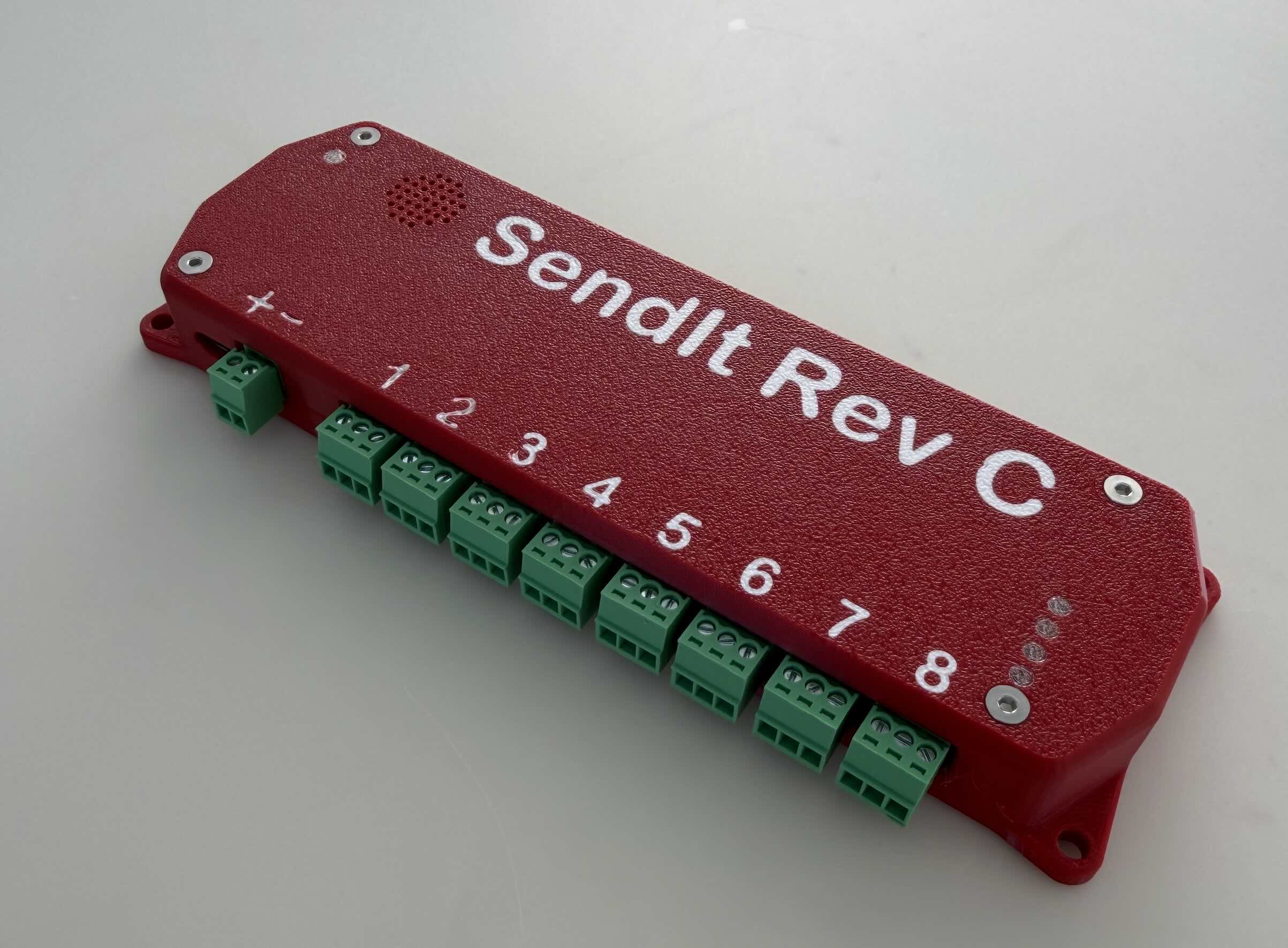
SendIt Revision C
Features
- ESP32-S3 module with WiFi and USB-C
- Powered by USB-C or 12–30 V DC external input, with onboard power regulation
- 8 x 16-bit ADC channels (ADS1115)
- 5 input type circuits, selectable by jumper
- Per-channel supply voltage: External / 24v / 5v / 3.3v
- 30mA resettable fuse on sensor supply
- Built-in 24v power supply for 4-20ma sensors
- I²C expansion (QWIIC connector)
- Unused I/O broken out as 2.54mm pin headers
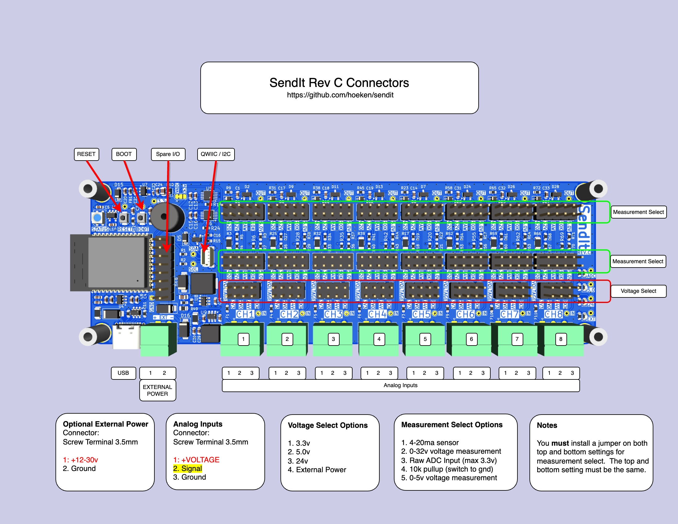
Hardware Pinout
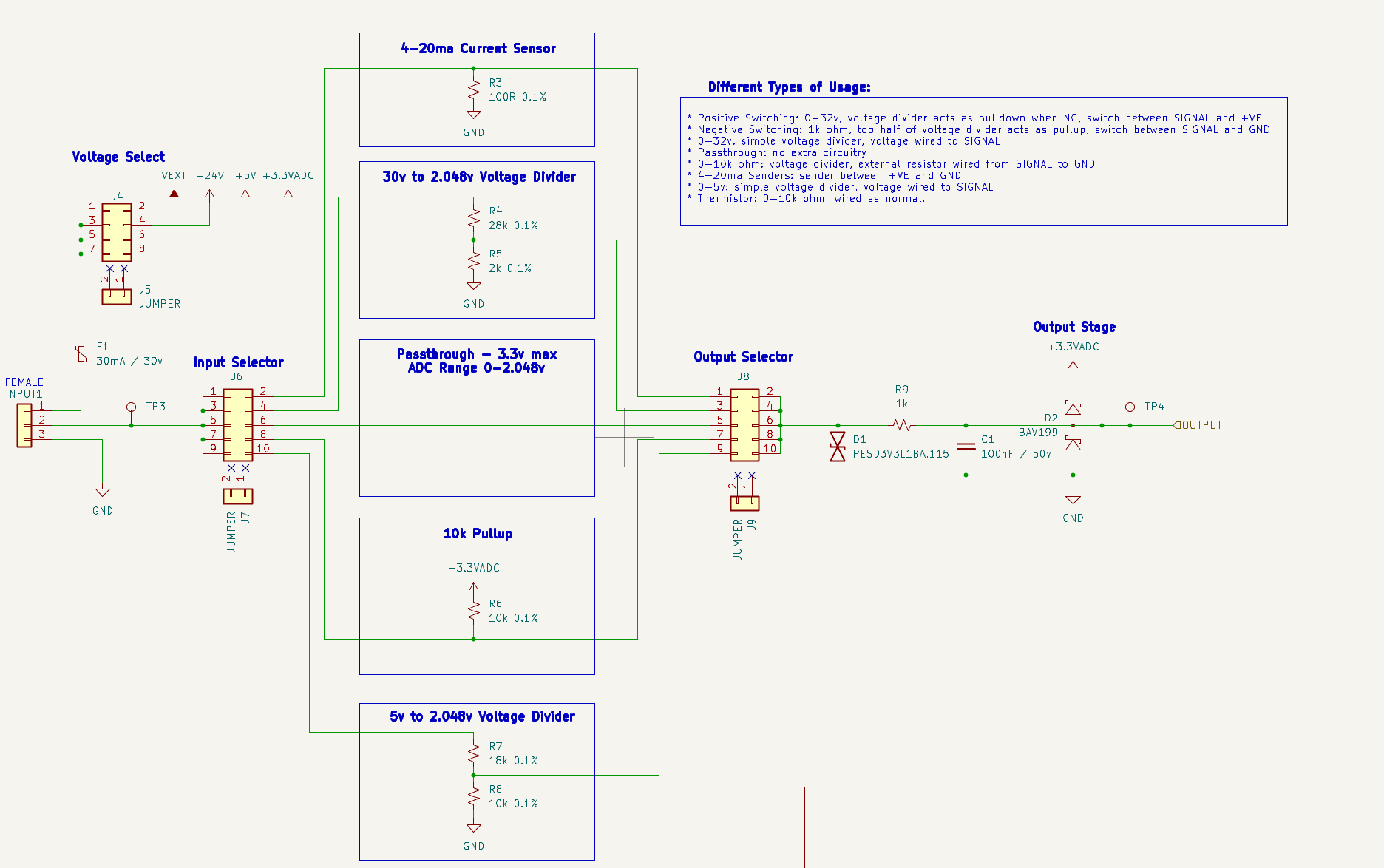
ADC Input Channel Schematic
Voltage Options
SendIt has 4 different supply voltages available that can be selected by using a jumper shunt on a per-channel basis:
- 24v (max 150mA total) usually for powering 4-20mA sensors
- 5v (max 500mA total)
- 3.3v (max 500mA total)
- External Supply (supplied via connector)
Each channel has a 30mA resettable fuse on the supply voltage.
Measurement Options
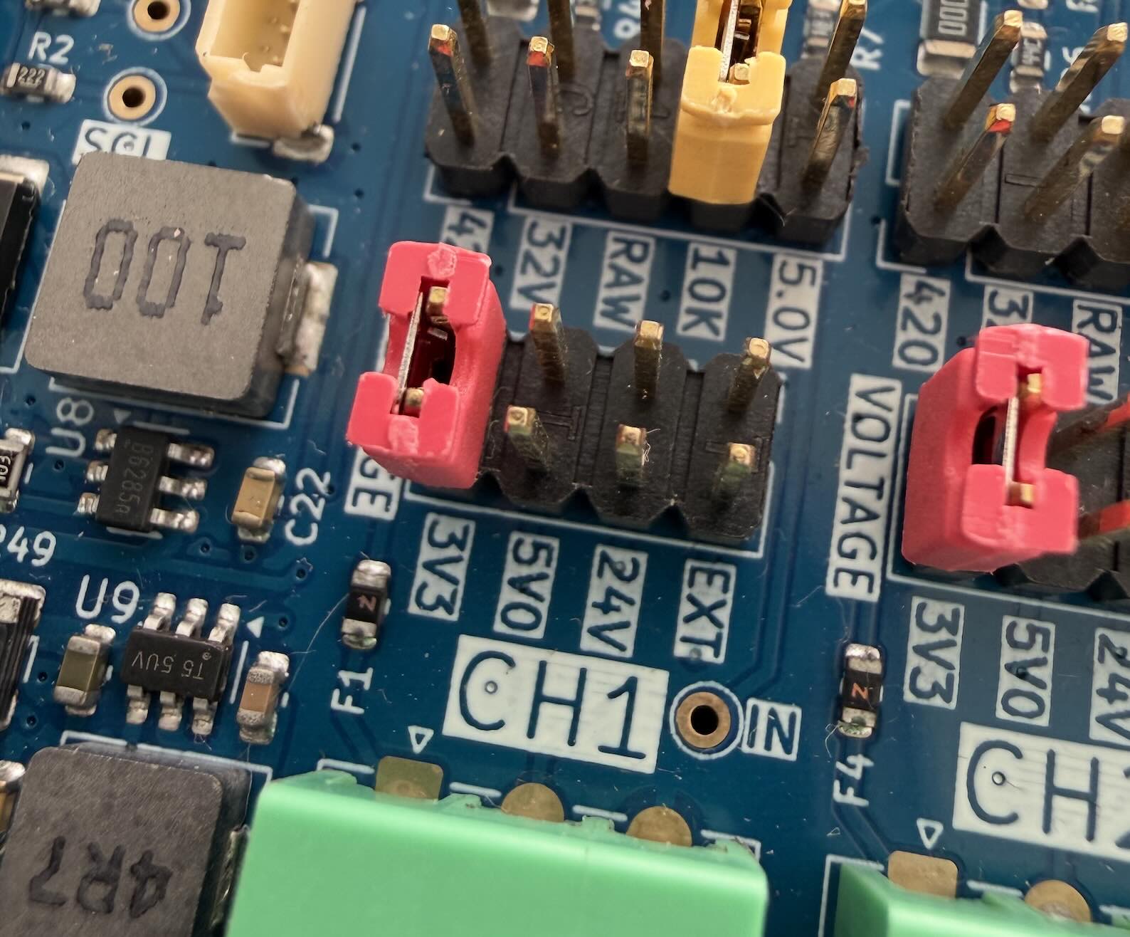
SendIt has 5 different measurement types that can be selected by using jumper shunts to configure the board on a per-channel basis.
Revision C has the following built-in hardware measurement circuits:
- 4-20ma sensors
- 0-32v input
- Raw ADC input
- 10k pullup to 3.3v
- 0-5v input
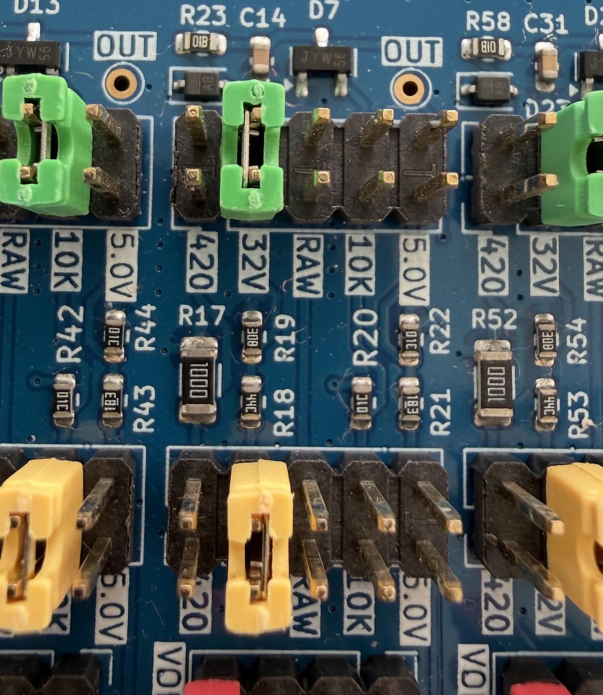
Each channel has two jumper positions to set measurement type — refer to the Measurement Select photo above. Install a jumper shunt on both positions (top and bottom) for the same measurement type. Mismatched jumpers will produce incorrect readings.
4-20ma Transducers / Senders
4-20mA senders are very common sensors for a variety of applications.
- Select an appropriate voltage for your sender. 24v is fairly standard.
- Select 420 as your measurement type.
- Wire your sender with the positive/supply wire to +VE and the negative/return wire to SIGNAL
If you need to power a large number of 4-20mA sensors, it is best to provide an external power supply and select that as the supply voltage. The 24v regulator on the board is somewhat small and may overheat.
After wiring, set the software Input Type to 4-20mA Sensor.
240-30 ohm / 0-180 ohm / 0-190 ohm Senders
Resistive senders are commonly used as tank level sensors for water and fuel tanks. You will need an external 150 ohm resistor to build this circuit. Larger resistor values also work, but reduce the accuracy slightly. 1k is probably about the maximum you would want to use. Use resistors with a tolerance of 1% or better and a minimum wattage of 1/10W (100mW)
- Select 3.3v as your voltage
- Wire your resistor between +VOLTAGE and SIGNAL
- Wire your sender between SIGNAL and GROUND
After wiring, set the software Input Type to Raw Output, then use a calibration table to map voltage readings to your desired unit (e.g., percentage or liters).
Positive Switching
- Select either 3.3v or 24v as your voltage
- Select the measurement type that matches the voltage range being switched:
- Use 5v if the switched voltage is 5 V or below
- Use 32v if the switched voltage is above 5 V (e.g., 12 V or 24 V systems)
- Wire your switch between +VOLTAGE and SIGNAL
After wiring, set the software Input Type to Digital Input.
Negative Switching
- Select 10K as your measurement type.
- Wire your switch between SIGNAL and GND
After wiring, set the software Input Type to Digital Input.
The 10K measurement type is also used for thermistors. Both use a resistive element between SIGNAL and GND with the onboard 10k pull-up to form a voltage divider.
0-32v Input
- Select 32v as your measurement type
- Wire your voltage to SIGNAL and ground to GROUND
After wiring, set the software Input Type to 0-32v Input.
0-5v Input
- Select 5v as your measurement type
- Wire your voltage to SIGNAL and ground to GROUND
After wiring, set the software Input Type to 0-5v Input.
Thermistor
- Select 10K as your measurement type
- Wire your thermistor between SIGNAL and GROUND
After wiring, set the software Input Type to Thermistor.
The 10K measurement type is also used for negative-switching inputs. See Negative Switching above.
Custom Input Voltage
If you have a nonstandard input voltage that doesn’t fit the 0-5v range, or the 0-32v range, you can use a custom voltage divider to translate your voltage into a range suitable for SendIt.
- Select your resistors using the TI Voltage Divider Calculator
- Input Voltage - your maximum input voltage
- Desired Output Voltage - 2.048
- Resistor Sequence - E24 (more common)
- Resistor Scale - 10000
- Set your measurement type to RAW
- Wire up your custom voltage divider. Use 1% resistors for best accuracy.
- R1 between YOUR SENSOR and SIGNAL
- R2 between SIGNAL and GROUND
- +VOLTAGE and GROUND to your sensor as appropriate.
After wiring, set the software Input Type to Raw Output, then use a calibration table to map the raw voltage to your desired unit.
Custom Circuit
You can connect your own analog signal directly to the ADC pin of the ADS1115 if needed. The ADS1115 is configured to measure from 0-2.048v by default. Do not exceed 3.3v on this pin, or you risk damaging the board.
- Select RAW as your measurement type
- Wire your sensor as needed.
- If you have a higher voltage, consider using the 0-5v circuit instead.
After wiring, set the software Input Type to Raw Output.
Source Files
Software Settings
After you have selected your hardware settings and wired up your sensors, you need to set the appropriate settings in software to let SendIt know how to interpret the readings.
Manufacturing
If you would like to manufacture your own boards, follow the instructions below:
Kicad File Preparation
- Install the Kicad Fabrication Toolkit plugin.
- From the PCB Editor, open Tools -> External Plugins -> Fabrication Toolkit
- Click Generate to create the production files.
- Upload the {board_name}.zip file in the first step of the JLC ordering process
- {board_name}_bom.csv file is the Bill of Materials for PCBA
- {board_name}_positions.csv file is the Component Placement file for PCBA
JLCPCB Ordering Options
If no option is specified below, use the default options provided by JLCPCB.
PCB
- PCB Color: Blue
- Surface Finish: ENIG
PCB Assembly
- Depanel Boards: YES
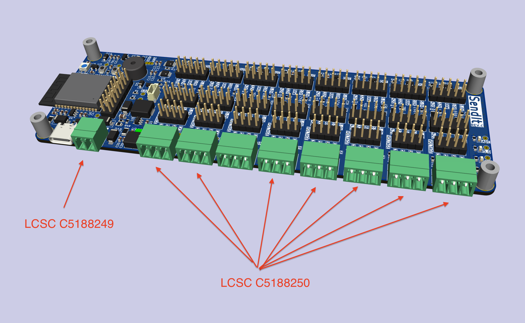
- PCBA Remark - attach image below
- PCBA Remark - add the text below
After production, insert the following parts:
INPUT6 - LCSC C5188249
INPUT1-INPUT5, INPUT7-INPUT9 - LCSC C5188250
Changelog
REV C
🔧 ADC & Analog Front-End
- Switched back to ADS1115 ADC.
- Removed the ADC VREF circuit and added a solder jumper for VREF selection.
- Standardized all analog scaling to 2.048 V reference (instead of 3.3 V).
- Added voltage dividers for 30 V and 5 V input ranges.
- Set 4–20 mA shunt resistor to 100 Ω.
- Added pull-up resistors on ADS1115 ALERT pin.
⚡ Power & Regulation
- Added a buck converter on the EXT port for 12/24 V → 5 V to power the ESP32.
- Includes a jumper to enable/disable EXT-port power.
- EXT port may now be used as power-only, reference-only, or both.
- Added 3.3 V ↔ 5.0 V buffer for WS2818 LED.
- Switched to green LEDs for power indication.
- Removed the USB-to-serial and USB hub for a simplified ESP32-S3 design.
🧩 Connectors & I/O
- Added QWIIC header.
- Moved pluggable terminal blocks down 0.5 mm.
- Removed jumper for EXT power selection.
🧪 Test Points
- Added test points for 3.3 V, 5.0 V, 24 V, GND, SDA, SCL, and others.
- Standardized all test points to 1.5×0.7 mm.
🔊 Piezo & Indicators
- Switched to passive piezo and added diode (Huaneng QMB-09B-03).
🧱 Mechanical & Layout
- Changed upper mounting holes to SMTSO3080CTJ hardware.
- Switched to SMT boot/reset buttons.
- Removed RTC clock crystal.
- Switched boost converter to MT3608B for 24 V generation.